Wednesday, February 27, 2013

STORED PROCEDURE T/F

 
STORED PROCEDURE T/F
  • Passive Transformation
  • Connected and Unconnected Transformation
  • Stored procedures are stored and run within the database.
A Stored Procedure transformation is an important tool for populating and Maintaining databases. Database administrators create stored procedures to Automate tasks that are too complicated for standard SQL statements.
Use of Stored Procedure in mapping:
  • Check the status of a target database before loading data into it.
  • Determine if enough space exists in a database.
  • Perform a specialized calculation.
  • Drop and recreate indexes. Mostly used for this in projects.
Data Passes Between IS and Stored Procedure One of the most useful features of stored procedures is the ability to send data to the stored procedure, and receive data from the stored procedure. There are three types of data that pass between the Integration Service and the stored procedure:
Input/output parameters: Parameters we give as input and the parameters returned from Stored Procedure.
Return values: Value returned by Stored Procedure if any.
Status codes: Status codes provide error handling for the IS during a workflow. The stored procedure issues a status code that notifies whether or not the stored procedure completed successfully. We cannot see this value. The IS uses it to determine whether to continue running the session or stop. Specifying when the Stored Procedure Runs
Normal: The stored procedure runs where the transformation exists in the mapping on a row-by-row basis. We pass some input to procedure and it returns some calculated values. Connected stored procedures run only in normal mode.
Pre-load of the Source: Before the session retrieves data from the source, the stored procedure runs. This is useful for verifying the existence of tables or performing joins of data in a temporary table.
Post-load of the Source: After the session retrieves data from the source, the stored procedure runs. This is useful for removing temporary tables.
Pre-load of the Target: Before the session sends data to the target, the stored procedure runs. This is useful for dropping indexes or disabling constraints.
Post-load of the Target: After the session sends data to the target, the stored procedure runs. This is useful for re-creating indexes on the database.
Using a Stored Procedure in a Mapping :
  1. Create the stored procedure in the database.
  2. Import or create the Stored Procedure transformation.
  3. Determine whether to use the transformation as connected or unconnected.
  4. If connected, map the appropriate input and output ports.
  5. If unconnected, either configure the stored procedure to run pre- or post-session, or configure it to run from an expression in another transformation.
  6. Configure the session.
Stored Procedures:
Connect to Source database and create the stored procedures given below:
CREATE OR REPLACE procedure sp_agg (in_deptno in number, max_sal out number,
min_sal out number, avg_sal out number, sum_sal out number)
As
Begin
select max(Sal),min(sal),avg(sal),sum(sal) into max_sal,min_sal,avg_sal,sum_sal
from emp where deptno=in_deptno group by deptno;
End;
/
CREATE OR REPLACE procedure sp_unconn_1_value(in_deptno in number, max_sal out number)
As
Begin
Select max(Sal) into max_sal from EMP where deptno=in_deptno;
End;
/
1. Connected Stored Procedure T/F
Example: To give input as DEPTNO from DEPT table and find the MAX, MIN, AVG and SUM of SAL from EMP table.
  • DEPT will be source table. Create a target table SP_CONN_EXAMPLE with fields DEPTNO, MAX_SAL, MIN_SAL, AVG_SAL & SUM_SAL.
  • Write Stored Procedure in Database first and Create shortcuts as needed.
Creating Mapping:
1. Open folder where we want to create the mapping.
2. Click Tools -> Mapping Designer.
3. Click Mapping-> Create-> Give name. Ex: m_SP_CONN_EXAMPLE
4. Drag DEPT and Target table.
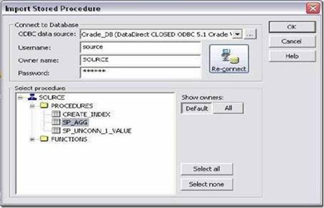
5. Transformation -> Import Stored Procedure -> Give Database Connection -> Connect -> Select the procedure sp_agg from the list.
clip_image030clip_image032
6. Drag DEPTNO from SQ_DEPT to the stored procedure input port and also to DEPTNO port of target.
7. Connect the ports from procedure to target as shown below:
8. Mapping -> Validate
9. Repository -> Save
  • Create Session and then workflow.
  • Give connection information for all tables.
  • Give connection information for Stored Procedure also.
  • Run workflow and see the result in table.
clip_image034
2. Unconnected Stored Procedure T/F :
An unconnected Stored Procedure transformation is not directly connected to the flow of data through the mapping. Instead, the stored procedure runs either:
  • From an expression: Called from an expression transformation.
  • Pre- or post-session: Runs before or after a session.
Method of returning the value of output parameters to a port:
  • Assign the output value to a local variable.
  • Assign the output value to the system variable PROC_RESULT. (See Later)
Example 1: DEPTNO as input and get MAX of Sal as output.
  • DEPT will be source table.
  • Create a target table with fields DEPTNO and MAX_SAL of decimal data type.
  • Write Stored Procedure in Database first and Create shortcuts as needed.
Creating Mapping:
1. Open folder where we want to create the mapping.
2. Click Tools -> Mapping Designer.
3. Click Mapping-> Create-> Give name. Ex: m_sp_unconn_1_value
4. Drag DEPT and Target table.
5. Transformation -> Import Stored Procedure -> Give Database Connection -> Connect -> Select the procedure sp_unconn_1_value from the list. Click OK.
6. Stored Procedure has been imported.
7. T/F -> Create Expression T/F. Pass DEPTNO from SQ_DEPT to Expression T/F.
8. Edit expression and create an output port OUT_MAX_SAL of decimal data type.
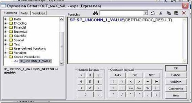
9. Open Expression editor and call the stored procedure as below:Click OK and connect the port from expression to target as in mapping below:
clip_image036
10. Mapping -> Validate
11. Repository Save.
  • Create Session and then workflow.
  • Give connection information for all tables.
  • Give connection information for Stored Procedure also.
  • Run workflow and see the result in table.
PROC_RESULT use:
  • If the stored procedure returns a single output parameter or a return value, we the reserved variable PROC_RESULT as the output variable.
Example: DEPTNO as Input and MAX Sal as output :
:SP.SP_UNCONN_1_VALUE(DEPTNO,PROC_RESULT)
  • If the stored procedure returns multiple output parameters, you must create variables for each output parameter.
Example: DEPTNO as Input and MAX_SAL, MIN_SAL, AVG_SAL and SUM_SAL
as output then:
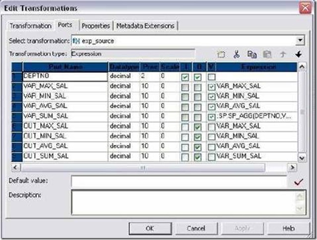
1. Create four variable ports in expression VAR_MAX_SAL,VAR_MIN_SAL, VAR_AVG_SAL and iVAR_SUM_SAL.
2. Create four output ports in expression OUT_MAX_SAL, OUT_MIN_SAL, OUT_AVG_SAL and OUT_SUM_SAL.
3. Call the procedure in last variable port says VAR_SUM_SAL.
:SP.SP_AGG (DEPTNO, VAR_MAX_SAL,VAR_MIN_SAL, VAR_AVG_SAL, PROC_RESULT)
Example 2:
DEPTNO as Input and MAX_SAL, MIN_SAL, AVG_SAL and SUM_SAL as O/P Stored Procedure to drop index in Pre Load of Target Stored Procedure to create index in Post Load of Target
  • DEPT will be source table. Create a target table SP_UNCONN_EXAMPLE with fields DEPTNO, MAX_SAL, MIN_SAL, AVG_SAL & SUM_SAL.
  • Write Stored Procedure in Database first and Create shortcuts as needed. Stored procedures are given below to drop and create index on target.Make sure to create target table first. Stored Procedures to be created in next example in Target Database:
clip_image007[4]clip_image038
Create or replace procedure CREATE_INDEX
As
Begin
Execute immediate 'create index unconn_dept on SP_UNCONN_EXAMPLE(DEPTNO)';
End;
/
Create or replace procedure DROP_INDEX
As
Begin
Execute immediate 'drop index unconn_dept';
End;
/
Creating Mapping:
1. Open folder where we want to create the mapping.
2. Click Tools -> Mapping Designer.
3. Click Mapping-> Create-> Give name. Ex: m_sp_unconn_1_value
4. Drag DEPT and Target table.
5. Transformation -> Import Stored Procedure -> Give Database Connection -> Connect -> Select the procedure sp_agg from the list. Click OK.
6. Stored Procedure has been imported.
7. T/F -> Create Expression T/F. Pass DEPTNO from SQ_DEPT to Expression T/F.
8. Edit Expression and create 4 variable ports and 4 output ports as shown below:
clip_image039clip_image041
9. Call the procedure in last variable port VAR_SUM_SAL.
10. :SP.SP_AGG (DEPTNO, VAR_MAX_SAL, VAR_MIN_SAL, VAR_AVG_SAL, PROC_RESULT)
11. Click Apply and Ok.
12. Connect to target table as needed.
13. Transformation -> Import Stored Procedure -> Give Database Connection for target -> Connect -> Select the procedure CREATE_INDEX and DROP_INDEX from the list. Click OK.
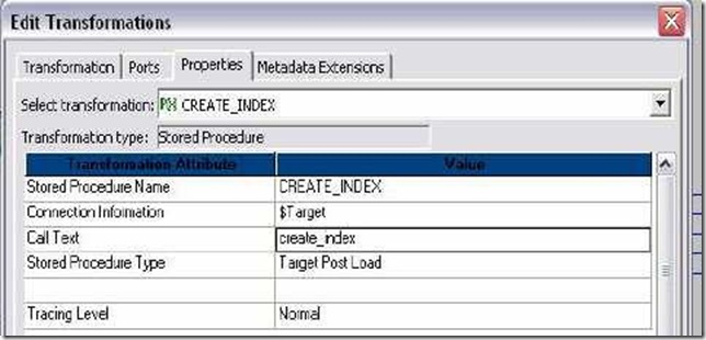
14. Edit DROP_INDEX -> Properties Tab -> Select Target Pre Load as Stored Procedure Type and in call text write drop_index. Click Apply -> Ok.
15. Edit CREATE_INDEX -> Properties Tab -> Select Target Post Load as Stored Procedure Type and in call text write create_index. Click Apply -> Ok.
16. Mapping -> Validate
17. Repository -> Save
  • Create Session and then workflow.
  • Give connection information for all tables.
  • Give connection information for Stored Procedures also.
  • Also make sure that you execute the procedure CREATE_INDEX on database before using them in mapping. This is because, if there is no INDEX on target table, DROP_INDEX will fail and Session will also fail.
  • Run workflow and see the result in table.
Tuesday, February 26, 2013

Normalizer Transformation

  • Active and Connected Transformation.
  • The Normalizer transformation normalizes records from COBOL and relational sources, allowing us to organize the data.
  • Use a Normalizer transformation instead of the Source Qualifier transformation when we normalize a COBOL source.
  • We can also use the Normalizer transformation with relational sources to create multiple rows from a single row of data.
Example 1: To create 4 records of every employee in EMP table.
  • EMP will be source table.
  • Create target table Normalizer_Multiple_Records. Structure same as EMP and datatype of HIREDATE as VARCHAR2.
  • Create shortcuts as necessary.
Creating Mapping :
  1. Open folder where we want to create the mapping.
  2. Click Tools -> Mapping Designer.
  3. Click Mapping-> Create-> Give name. Ex: m_ Normalizer_Multiple_Records
  4. Drag EMP and Target table.
  5. Transformation->Create->Select Expression-> Give name, Click create, done.
  6. Pass all ports from SQ_EMP to Expression transformation.
  7. Transformation-> Create-> Select Normalizer-> Give name, create & done.
  8. Try dragging ports from Expression to Normalizer. Not Possible.
  9. Edit Normalizer and Normalizer Tab. Add columns. Columns equal to columns in EMP table and datatype also same.
  10. Normalizer doesn’t have DATETIME datatype. So convert HIREDATE to char in expression t/f. Create output port out_hdate and do the conversion.
  11. Connect ports from Expression to Normalizer.
  12. Edit Normalizer and Normalizer Tab. As EMPNO identifies source records and we want 4 records of every employee, give OCCUR for EMPNO as 4.
  13. clip_image002
  14. Click Apply and then OK.
  15. Add link as shown in mapping below:
  16. Mapping -> Validate
  17. Repository -> Save
  • Make session and workflow.
  • Give connection information for source and target table.
  • Run workflow and see result.
Example 2: To break rows into columns
Source:
Roll_NumberNameENGHINDIMATHS
100Amit787690
101Rahul767887
102Jessie659879


Target :
Roll_NumberNameMarks
100Amit78
100Amit76
100Amit90
101Rahul76
101Rahul78
101Rahul87
102Jessie65
102Jessie98
102Jessie79

  • Make source as a flat file. Import it and create target table.
  • Create Mapping as before. In Normalizer tab, create only 3 ports Roll_Number, Name and Marks as there are 3 columns in target table.
  • Also as we have 3 marks in source, give Occurs as 3 for Marks in Normalizer tab.
  • Connect accordingly and connect to target.
  • Validate and Save
  • Make Session and workflow and Run it. Give Source File Directory and Source File name for source flat file in source properties in mapping tab of session.
  • See the result.


What is a Noramalizer Transformation?

In a snapshot, here is what a Normalizer is or does:
  • Active Transformation
  • Can output multiple rows for each input row
  • Can transpose the data (transposing columns to rows
A Normalizer is an Active transformation that returns multiple rows from a source row, it returns duplicate data for single-occurring source columns. The Normalizer transformation parses multiple-occurring columns from COBOL sources, relational tables, or other sources. Normalizer can be used to transpose the data in columns to rows.
Normalizer effectively does the opposite of what Aggregator does!

Transposing data using Normalizer

Let's imagine we have a table like below that stores the sales figure for 4 quarters of a year in 4 different columns. As you can see each row represent one shop and the columns represent the corresponding sales. Next, imagine - our task is to generate a result-set where we will have separate rows for every quarter. We can configure a Normalizer transformation to return a separate row for each quarter like below..
The following source rows contain four quarters of sales by store:
Source Table
StoreQuarter1Quarter2Quarter3Quarter4
Shop 1100300500700
Shop 2250450650850
The Normalizer returns a row for each shop and sales combination. It also returns an index - called GCID (we will know later in detail) - that identifies the quarter number:
Target Table
ShopSalesQuarter
Shop 11001
Shop 13002
Shop 15003
Shop 17004
Shop 22501
Shop 24502
Shop 26503
Shop 28504

How to use Normalizer transformation inside Informatica Mapping

Now that you know the concept of a normalizer, let's see how we can implement this concept using Normalizer transformation. We will take a different data set for our example this time. Suppose we have the following data in source:
NameMonthTransportationHouse RentFood
SamJan2001500500
JohnJan3001200300
TomJan3001350350
SamFeb3001550450
JohnFeb3501200290
TomFeb3501400350
and we need to transform the source data and populate this as below in the target table:
NameMonthExpense TypeExpense
SamJanTransport200
SamJanHouse rent1500
SamJanFood500
JohnJanTransport300
JohnJanHouse rent1200
JohnJanFood300
TomJanTransport300
TomJanHouse rent1350
TomJanFood350
Now below is the screen-shot of a complete mapping which shows how to achieve this result using Informatica PowerCenter Designer.
Normalization Mapping
Please click on the above image to enlarge it. You can see after the Source Qualifier, we have placed the Normalizer transformation. In the next section, I will explain how to set up the properties of the normalizer.

Setting Up Normalizer Transformation Property

First we need to set the number of occurrences property of the Expense head as 3 in the Normalizer tab of the Normalizer transformation. This is because we have 3 different types of expenses in the given data - Food, Houserent and Transportation.
As soon as we set the occurrences to 3, Normalizer will in turn automatically create 3 corresponding input ports in the ports tab along with the other fields (e.g. "Individual" and "Month" fields). These 3 input ports, as you can see in the above image, are EXPENSEHEAD_in1, EXPENSEHEAD_in2, EXPENSEHEAD_in3. We have connected these input ports with food, house rent and transportation from the source qualifier. Below image shows the setting up of number of occurrences property.
Normalizer Tab
Next, In the Ports tab of the Normalizer the ports will be created automatically as configured in the Normalizer tab.
But, Interestingly we will observe two new columns here. They are ,
  • GK_EXPENSEHEAD
  • GCID_EXPENSEHEAD
See these ports in the below screen shot. Again, if you need - please click on the image to enlarge it
Normalizer PORTS Tab GCID_
GK field generates sequence number starting from the value as defined in Sequence field while GCID holds the value of the occurrence field i.e. the column no of the input Expense head.
In our case, 1 is for FOOD, 2 is for HOUSERENT and 3 is for TRANSPORTATION. Now the GCID will give which expense corresponds to which field while converting columns to rows.
Below is the screen-shot of the expression to handle this GCID efficiently:
Normalization Expression GCID
As you can see above, the DECODE statement is used to assign proper level to the output expense head field

Sorter Transformation in Informatica

Sorter transformation is an active and connected transformation used to sort the data. The data can be sorted in ascending or descending order by specifying the sort key. You can specify one or more ports as a sort key and configure each sort key port to sort in ascending or descending order. You can also configure the order of the ports in which the integration service applies to sort the data.

The sorter transformation is used to sort the data from relational or flat file sources. The sorter transformation can also be used for case-sensitive sorting and can be used to specify whether the output rows should be distinct or not.

Creating Sorter Transformation

Follow the below steps to create a sorter transformation

  1. In the mapping designer, create a new mapping or open an existing mapping
  2. Go the toolbar->Click on Transformation->Create
  3. Select the Sorter Transformation, enter the name, click on create and then click on Done.
  4. Select the ports from the upstream transformation and drag them to the sorter transformation. You can also create input ports manually on the ports tab.
  5. Now edit the transformation by double clicking on the title bar of the transformation.
  6. Select the ports you want to use as the sort key. For each selected port, specify whether you want the integration service to sort data in ascending or descending order.


Configuring Sorter Transformation

Configure the below properties of sorter transformation

  • Case Sensitive: The integration service considers the string case when sorting the data. The integration service sorts the uppercase characters higher than the lowercase characters.
  • Work Directory: The integration service creates temporary files in the work directory when it is sorting the data. After the integration service sorts the data, it deletes the temporary files.
  • Distinct Output Rows: The integration service produces distinct rows in the output when this option is configured.
  • Tracing Level: Configure the amount of data needs to be logged in the session log file.
  • Null Treated Low: Enable the property, to treat null values as lower when performing the sort operation. When disabled, the integration service treats the null values as higher than any other value.
  • Sorter Cache Size: The integration service uses the sorter cache size property to determine the amount of memory it can allocate to perform sort operation

Performance improvement Tip

Use the sorter transformation before the aggregator and joiner transformation and sort the data for better performance.

Sorter Transformation Examples

1. Create a mapping to sort the data of employees on salary in descending order?

2. Create a mapping to load distinct departments into the target table?

Sorter Transformation


Sorter Transformation
  • Connected and Active Transformation
  • The Sorter transformation allows us to sort data.
  • We can sort data in ascending or descending order according to a specified sort key.
  • We can also configure the Sorter transformation for case-sensitive sorting, and specify whether the output rows should be distinct.
When we create a Sorter transformation in a mapping, we specify one or more ports as a sort key and configure each sort key port to sort in ascending or descending order. We also configure sort criteria the Power Center Server applies to all sort key ports and the system resources it allocates to perform the sort operation.
The Sorter transformation contains only input/output ports. All data passing through the Sorter transformation is sorted according to a sort key. The sort key is one or more ports that we want to use as the sort criteria.
Sorter Transformation Properties
1. Sorter Cache Size:
The Power Center Server uses the Sorter Cache Size property to determine the maximum amount of memory it can allocate to perform the sort operation. The Power Center Server passes all incoming data into the Sorter transformation Before it performs the sort operation.
  • We can specify any amount between 1 MB and 4 GB for the Sorter cache size.
  • If it cannot allocate enough memory, the Power Center Server fails the Session.
  • For best performance, configure Sorter cache size with a value less than or equal to the amount of available physical RAM on the Power Center Server machine.
  • Informatica recommends allocating at least 8 MB of physical memory to sort data using the Sorter transformation.
2. Case Sensitive:
The Case Sensitive property determines whether the Power Center Server considers case when sorting data. When we enable the Case Sensitive property, the Power Center Server sorts uppercase characters higher than lowercase characters.
3. Work Directory
Directory Power Center Server uses to create temporary files while it sorts data.
4. Distinct:
Check this option if we want to remove duplicates. Sorter will sort data according to all the ports when it is selected.
clip_image002
Example: Sorting data of EMP by ENAME
  • Source is EMP table.
  • Create a target table EMP_SORTER_EXAMPLE in target designer. Structure same as EMP table.
  • Create the shortcuts in your folder.
Creating Mapping:
1. Open folder where we want to create the mapping.
2. Click Tools -> Mapping Designer.
3. Click Mapping-> Create-> Give mapping name. Ex: m_sorter_example
4. Drag EMP from source in mapping.
5. Click Transformation -> Create -> Select Sorter from list. Give name and click Create. Now click done.
6. Pass ports from SQ_EMP to Sorter Transformation.
7. Edit Sorter Transformation. Go to Ports Tab
8. Select ENAME as sort key. CHECK mark on KEY in front of ENAME.
9. Click Properties Tab and Select Properties as needed.
10. Click Apply -> Ok.
11. Drag target table now.
12. Connect the output ports from Sorter to target table.
13. Click Mapping -> Validate
14. Repository -> Save
  • Create Session and Workflow as described earlier. Run the Workflow and see the data in target table.
  • Make sure to give connection information for all tables.
Sample Sorter Mapping :
clip_image002[5]
Performance Tuning:
Sorter transformation is used to sort the input data.
  1. While using the sorter transformation, configure sorter cache size to be larger than the input data size.
  2. Configure the sorter cache size setting to be larger than the input data size while Using sorter transformation.
  3. At the sorter transformation, use hash auto keys partitioning or hash user keys Partitioning.


Difference between Informatica and Datastage

Both Datastage and Informatica are powerful ETL tools . Both tools do almost exactly the same thing in almost exactly the same way. Performance, maintainability, learning curve are all similar and comparable. Below are the few things which I would like highlight regarding both these tools.
Multiple Partitions
Informatica offers partitioning as dynamic partitioning which defaults a workflow not at every Stage/Object level in a mapping/job. Informatica offers other partitioning choices as well at the workflow level.
DataStage's pipeline partitioning uses multiple partitions, processed and then re-collected with DataStage. DataStage lets control a job design based on the logic of the processing instead of defaulting the whole pipeline flow to one partition type.  DataStage offers 7 different types of multi-processing partitions.
User Interface
Informatica offers access to the development and monitoring effort through its 4 GUIs - offered as Informatica PowerDesigner, Repository Manager, Worflow Designer, Workflow Manager.  

DataStage caters to development and monitoring its jobs through 3 GUIs - IBM DataStage Designer(for development), Job Sequence Designer(workflow design) and Director(for monitoring).
Version Control
Informatica offers instant version control through its repository server managed with “Repository Manager” GUI console. A mapping with work-in-progress cannot be opened until saved and checked back into the repository. Version control is done by using checkin and check out.
Version Control was offered as a component until version Ascential DataStage7.5.x. Ascential was acquired by IBM and when DataStage was integrated into IBM Information Server with DataStage at version 8.0.1, the support of version control as a component was discontinued.

Repository based flow
Informatica, offers a step-by-step effort of creating a data integration solution. Each object created while mapping a source with a target gets saved into the repository project folder categorized by - Sources, Targets, Transformations, Mappings, Mapplets, User-defined functions, Business Components, Cubes and Dimensions. Each object created can be shared, dropped into a mapping across cross-functional development teams. Thus increasing re-usability. Projects are folder based and inter-viewable. 

DataStage offers a project based integration solution, projects are not interviewable. Every project needs a role based access. The step-by-step effort in mapping a source to a target lineages into a job. For sharing objects within a job, separate objects need to be created called containers that are local/shared.
Data Encryption
Informatica has an offering within PowerCenter Designer as a separate transformation called “Data Masking Transformation”.
Data Masking or encryption needs to be done before reaching DataStage Server.
Variety of Transformations
Informatica offers about 30 general transformations for processing incoming data. 
Datastage offers about 40 data transforming stages/objects. Datastage is more powerful transformation engine by using functions (Oconv and IConv) and routines. We can do almost any transformation.
Source_- Target flow
Within Informatica’s PowerCenter Designer, first a source definition needs to be created using “Source Analyzer” that imports the metadata, then a target definition is created using “Target Designer”, then a transformation using “Transformation Developer” is created, and finally maps a source-transformation-target using “Mapping Designer”.

Datastage lets drag and drop a functionality i.e a stage within in one canvas area for a pipeline source-target job. With  DataStage within the “DataStage Designer” import of both source and target metadata is needed, proceeding with variety of stages offered as database stages, transformation stages, etc.

The biggest difference between both the vendor offerings in this area is Informatica forces you to be organized through a step-by-step design process, while DataStage leaves the organization as a choice and gives you flexibility in dragging and dropping objects based on the logic flow.
Checking Dependencies
Informatica offers a separate edition – Advanced edition that helps with data lineage and impact analysis. We can go to separate targets and source and check all the dependencies on that.
DataStage offers through Designer by right clicking on a job to perform dependencies or impact analysis.
Components Used
The Informatica ETL transformations are very specific purpose, so you tend to need more boxes on the page to do the same thing. eg. A simple transform in Informatica would have a Source Table, Source Qualifier, Lookup, Router, 2 Update Strategies, and 2 Target Tables (9 boxes).
In DataStage, you would have a Table and Hashed File for the lookup, plus a Source Relational Stage, Transformation Stage, and 2 links to a target Relational Stage (5 boxes). This visual clutter in Informatica is a bit annoying.

Type of link
To link two components in Informatica, you have to link at the column level.We have to connect each and every column bw the two componenents
In DataStage, you link at the component level, and then map individual columns. This allows you to have coding templates that are all linked up - just add columns. I find this a big advantage in DS.
Reusability
Informatica offers ease of re-usability through Mapplets and Worklets for re-using mappings and workflows.This really improves the performance
DataStage offers re-usability of a job through containers(local&shared). To re-use a Job Sequence(workflow), you will need to make a copy, compile and run.

Code Generation and Compilation
Informatica’s thrust is the auto-generated code. A mapping gets created by dropping a source-transformation-target that doesn’t need to be compiled.
DataStage requires to compile a job in order to run it successfully.

Heterogeneous Sources
In Informatica we can use both heterogenous source and homogenous source.
Datastage does not perform very well with heterogeneous sources. You might end up extracting data from all the sources and putting them into a hash and start your transformation
Slowly Changing Dimension
Informatica supports Full History, Recent Values, Current & Previous Values using SCD wizards.
DataStage supports only through Custom scripts and does not have a wizard to do this
Dynamic Lookup Cache

Informatica's marvellous Dynamic Cache Lookup has no equivalent in DS Server Edition. The same saves some effort and is very easily maintainable.

What is XML Transformation in Informatica

XML Transformations
In this post we will see what the different types of XML Transformation are
  • XML Source Qualifier Transformation
  • XML Parser Transformation
  • XML Generator Transformation Overview
 XML Source Qualifier Transformation
It’s an Active Transformation, as well as Connected.
Just like the normal SourceQualifier Transformation we can use the XML Source Qualifier Transformation by dragging an XML source definition to the Mapping Designer workspace or by manually creating one. The source definition needs to be connected to the target via XML Source Qualifier Transformation. This Source qualifier defines the data elements that the Integration Service reads when it executes a session.
XML Source Qualifier has one input or output port for every column in the source. If you remove an XML source definition from a mapping, the Designer also removes the corresponding XML Source Qualifier transformation. But we can link one XML source definition to one XML Source Qualifier transformation.
Also we can link ports of XML Source Qualifier Transformation to ports of different transformations
XML Parser Transformation
It’s an Active Transformation, as well as Connected.
We use an XML Parser transformation to extract XML inside a pipeline and then pass this to the target.
The XML is extracted from the source systems such as files or databases. The XML Parser transformation reads XML data from a single input port and writes data to one or more output ports.
XML Generator Transformation Overview
It’s an Active Transformation, as well as Connected.
We use XML Generator Transformation Overview to create XML inside a pipeline. It reads data from source such as files and databases and generates XML in the pipeline. The XML Generator transformation accepts data from multiple ports and writes XML through a single output port.

Difference between Router and Filter transformation in Informatica

Router
Filter
Router transformation provides us the facility to capture the rows of data that do not meet any of the conditions to a default output group.
A Filter transformation tests data for one condition and drops the rows of data that do not meet the condition.
Router transformation is a single input and multi output group transformation.
Filter is single input and single output group transformation.
In a router transformation, you can specify more than one filter condition.
Filter transformation, you can specify only one filter condition.
The router transformation does not block input rows and those records that failed the filter condition will be passed to the default group
In a filter transformation there is chance that records get blocked
Router transformation acts like IIF condition in informatica or CASE.. WHEN in database.
Filter transformation works as WHERE clause of SQL .

Advantages of Router Transformation over Filter Transformation
  • Better Performance; because in mapping, the Router transformation Informatica server processes the input data only once instead of as many times as you have conditions in Filter transformation.
  • Less complexity; because we use only one Router transformation instead of multiple Filter transformation.
  • Router transformation  is more efficient than the Filter transformation.
For Eg:
We have 3 departments in source now we want to send these records into 3 tables.To achieve this we require only one Router transformation.In case we want to get same result with Filter transformation then we require at least 3 Filter transformations.
Similarity:
A Router and Filter transformation are almost same because both transformations allow you to use a condition to test data.

All About Informatica Transformations


In Informatica, Transformations help us to transform the source data according to the requirements of target system and thereby ensuring the quality of the data being loaded into target.
Transformations mainly are of two types: Active and Passive.
Active Transformation
An active transformation can change the number of rows that pass through it from source to target i.e it eliminates rows that do not meet the condition in transformation.
Passive Transformation
A passive transformation does not change the number of rows that pass through it i.e it passes all rows through the transformation.
Transformations can be Connected or UnConnected.
Connected Transformation
Connected transformation is connected to other transformations or directly to target table in the mapping.
UnConnected Transformation
An unconnected transformation is not connected to other transformations in the mapping. It is called within another transformation, and returns a value to that transformation.
List of Transformations
Below are the list of Transformations available in
Informatica PowerCenter:
  • Aggregator Transformation
  • Expression Transformation
  • Filter Transformation
  • Joiner Transformation
  • Lookup Transformation
  • Normalizer Transformation
  • Rank Transformation
  • Router Transformation
  • Sequence Generator Transformation
  • Stored Procedure Transformation
  • Sorter Transformation
  • Update Strategy Transformation
  • XML Source Qualifier Transformation
  • Advanced External Procedure Transformation
  • External Transformation
  • Union Transformation
Now we will discuss in detail, about the Informatica Transformations and their significances in the ETL process.
Aggregator Transformation
Aggregator transformation is an Active and Connected transformation. This transformation is useful to perform calculations such as averages and sums (mainly to perform calculations on multiple rows or groups). For example, to calculate total of daily sales or to calculate average of monthly or yearly sales. Aggregate functions such as AVG, FIRST, COUNT, PERCENTILE, MAX, SUM etc. can be used in aggregate transformation.
Expression Transformation
Expression transformation is a Passive and Connected transformation. This can be used to calculate values in a single row before writing to the target. For example, to calculate discount of each product or to concatenate first and last names or to convert date to a string field.
Filter Transformation
Filter transformation is an Active and Connected transformation. This can be used to filter rows in a mapping that do not meet the condition. For example, to know all the employees who are working in Department 10 or to find out the products that falls between the rate category $500 and $1000.
Joiner Transformation
Joiner Transformation is an Active and Connected transformation. This can be used to join two sources coming from two different locations or from same location. For example, to join a flat file and a relational source or to join two flat files or to join a relational source and a XML source. In order to join two sources, there must be at least one matching port. While joining two sources it is a must to specify one source as master and the other as detail. The Joiner transformation supports the following types of joins:
  • Normal
  • Master Outer
  • Detail Outer
  • Full Outer
Normal join discards all the rows of data from the master and detail source that do not match, based on the condition.
Master outer join discards all the unmatched rows from the master source and keeps all the rows from the detail source and the matching rows from the master source.
Detail outer join keeps all rows of data from the master source and the matching rows from the detail source. It discards the unmatched rows from the detail source.
Full outer join keeps all rows of data from both the master and detail sources.
Lookup Transformation
Lookup transformation is Passive and it can be both Connected and UnConnected as well. It is used to look up data in a relational table, view, or synonym. Lookup definition can be imported either from source or from target tables.
For example, if we want to retrieve all the sales of a product with an ID 10 and assume that the sales data resides in another table. Here instead of using the sales table as one more source, use Lookup transformation to lookup the data for the product, with ID 10 in sales table.
Difference between Connected and UnConnected Lookup Transformation:
  • Connected lookup receives input values directly from mapping pipeline whereas UnConnected lookup receives values from:LKP expression from another transformation.
  • Connected lookup returns multiple columns from the same row whereas UnConnected lookup has one return port and returns one column from each row.
  • Connected lookup supports user-defined default values whereas UnConnected lookup does not support user defined values.
Normalizer Transformation
Normalizer Transformation is an Active and Connected transformation. It is used mainly with COBOL sources where most of the time data is stored in de-normalized format. Also, Normalizer transformation can be used to create multiple rows from a single row of data.
Rank Transformation
Rank transformation is an Active and Connected transformation. It is used to select the top or bottom rank of data. For example, to select top 10 Regions where the sales volume was very high or to select 10 lowest priced products.
Router Transformation
Router is an Active and Connected transformation. It is similar to filter transformation. The only difference is, filter transformation drops the data that do not meet the condition whereas router has an option to capture the data that do not meet the condition. It is useful to test multiple conditions. It has input, output and default groups. For example, if we want to filter data like where State=Michigan, State=California, State=New York and all other States. It’s easy to route data to different tables.
Sequence Generator Transformation
Sequence Generator transformation is a Passive and Connected transformation. It is used to create unique primary key values or cycle through a sequential range of numbers or to replace missing keys.
It has two output ports to connect transformations. By default it has two fields CURRVAL and NEXTVAL(You cannot add ports to this transformation). NEXTVAL port generates a sequence of numbers by connecting it to a transformation or target. CURRVAL is the NEXTVAL value plus one or NEXTVAL plus the Increment By value.
Stored Procedure Transformation
Stored Procedure transformation is a Passive and Connected & UnConnected transformation. It is useful to automate time-consuming tasks and it is also used in error handling, to drop and recreate indexes and to determine the space in database, a specialized calculation etc.
The stored procedure must exist in the database before creating a Stored Procedure transformation, and the stored procedure can exist in a source, target, or any database with a valid connection to the Informatica Server. Stored Procedure is an executable script with SQL statements and control statements, user-defined variables and conditional statements. In case of stored procedure transformation procedure will be compiled and executed in a relational data source. You need data base connection to import the stored procedure in to your mapping.
Sorter Transformation
Sorter transformation is a Connected and an Active transformation. It allows to sort data either in ascending or descending order according to a specified field. Also used to configure for case-sensitive sorting, and specify whether the output rows should be distinct.
Source Qualifier Transformation
Source Qualifier transformation is an Active and Connected transformation. When adding a relational or a flat file source definition to a mapping, it is must to connect it to a Source Qualifier transformation. The Source Qualifier performs the various tasks such as overriding default SQL query, filtering records; join data from two or more tables etc.
Update Strategy Transformation
Update strategy transformation is an Active and Connected transformation. It is used to update data in target table, either to maintain history of data or recent changes. You can specify how to treat source rows in table, insert, update, delete or data driven.
XML Source Qualifier Transformation
XML Source Qualifier is a Passive and Connected transformation. XML Source Qualifier is used only with an XML source definition. It represents the data elements that the Informatica Server reads when it executes a session with XML sources.
Advanced External Procedure Transformation
Advanced External Procedure transformation is an Active and Connected transformation. It operates in conjunction with procedures, which are created outside of the Designer interface to extend PowerCenter/PowerMart functionality. It is useful in creating external transformation applications, such as sorting and aggregation, which require all input rows to be processed before emitting any output rows.
Union Transformation
The union transformation is used to merge multiple datasets from various streams or pipelines into one dataset. This transformation works similar to the UNION ALL, it does not remove any duplicate rows. It is recommended to use aggregator to remove duplicates are not expected at the target.
External Procedure Transformation
External Procedure transformation is an Active & Connected/UnConnected transformations. Sometimes, the standard transformations such as Expression transformation may not provide the functionality that you want.In such cases External procedure is useful to develop complex functions within a dynamic link library (DLL) or UNIX shared library, instead of creating the necessary Expression transformations in a mapping.
Differences between Advanced External Procedure and External Procedure Transformations:
  • External Procedure returns single value, where as Advanced External Procedure returns multiple values.
  • External Procedure supports COM and Informatica procedures where as AEP supports only Informatica Procedures.